A cheap, small, convenient, reliable, and durable lab-on-a-chip is needed for various scenarios in practical applications. The authors hope to use the chip only after plugging in a mobile phone. An ideal micropump design is obtained by simplifying the micropump theory, reducing the micropump to 1 mm (oscillator pump, O-pump), the external device (actuator) to 5 mm, and the power to 10 mW. This system costs ≈$10 and can work in harsh fluid environments (such as animal cell culture) for an extended period (a few months of testing). An MP3 player drives two O-pumps by a programmable playlist. The O-pump is a permanent magnet positive sphere in an open fluid space, which is not easy to block and rolls freely without wear. Only controlled by the magnetic field, the O-pump avoids interference from the current, electric field, and chemical activity. The fluid is driven by a vibrating motion, in open or sealed channels, with no unique materials and no other equipment. The debris, bubbles, and fibers in the blood viscosity fluid do not affect the pump's function. The system can be applied in different scenarios, such as the automatic cultivation of stem cells or point-of-care devices.
Micropump applications face many engineering difficulties.[1] Micropumps continue to solve specific challenges in the evolution process but leave others (Table 1[a–i]). For example, a gravity[2] vacuum[3, 4] drive loses velocity accuracy. Perfusion[5-11] uses syringes that destroy the microenvironment. The stirred pump[12] has a sealing problem. Diaphragm pumps[13, 14] need deformable materials that are imperfect in optical, biocompatibility. Ferrofluid,[15] electroosmotic,[16] or electrochemical[17] technology bring chemical interference and voltage interference. The surface tension pump[18] is prone to clogging by dirt. The acoustic wave pump[19, 20] does not entirely avoid elastic materials and high energy. The electrowetting-on-dielectric technology[21] cannot provide continuous flow and avoid electricity. Real applications urgently need the ideal micropump. The ideal micropump needs to push the fluid in the space to move in a direction under the most simplified conditions. Any non-essential design brings additional costs and engineering difficulties. We theoretically hope to get the ideal micropump and solve as many problems as possible at one time. In this paper, the 1D oscillator in the inertial fluid is used as the fluid drive principle. The scanning magnetic field controls a magnetic beads’ frequency and amplitude for quantitative fluxes, avoiding factors not relating to the core function to the greatest extent and obtaining a highly programmable magnetic micropump. This pump can generally work in a liquid environment that is more than twice the blood viscosity and full of debris and fibers. It has a consumption of 10 mW and long life, programmed and driven by mobile phone audio. It is very suitable for cell culture and development into point-of-care microfluidic devices.
| Evolution | Microfluidic pumps | 1 | 2 | 3 | 4 | 5 | 6 | 7 | 8 | 9 | 10 | |
|---|---|---|---|---|---|---|---|---|---|---|---|---|
| Flow rate control | Internal circulation system | No seal isolation | No deformation diaphragm | Chemically inert materials | Can be open or closed | Simple structure; No interface | Ultralow cost [no equipment] | Ultrasmall size | Ultralow power consumption | |||
| i | ↑ ↑ ↑ ↑ ↑ ↑ ↑ ↑ ↑ ↑ ↑ ↑ ↑ ↑ ↑ ↑ ↑ ↑ ↑ ↑ | Oscillator pump (O-pump, this study) | ✓ | ✓ | ✓ | ✓ | ✓ | ✓ | ✓ | <$10 | 1.5 mm | 10 mW |
| h | Ideal pump | ✓ | ✓ | ✓ | ✓ | ✓ | ✓ | ✓ | →0 | →0 | →0 | |
| g | Acoustic wave-based[19, 20] | ✓ | ✓ | ✓ | ? | ✓ | ? | ⨯ | – | – | – | |
| f | Surface tension pump[18] | ✓ | ✓ | ✓ | ✓ | ✓ | ⨯ | – | – | – | – | |
| e | Liquid metal pump,[22] | ✓ | ✓ | ✓ | ✓ | ⨯ | – | – | – | – | – | |
| d | Diaphragm,[23] soft biomimetic[24] | ✓ | ✓ | ✓ | ⨯ | – | – | – | – | – | – | |
| c | Stirrer-based[25] | ✓ | ✓ | ⨯ | – | – | – | – | – | – | – | |
| b | Peristaltic,[26, 27] syringe,[28] balloon,[29] high performance liquid chromatography,[30] | ✓ | ⨯ | – | – | – | – | – | – | – | – | |
| a | Gravity,[33] centrifugal,[34] capillary,[35] osmosis,[36] cell,[37] effervescent reaction,[38] water-activated[39] | ⨯ | – | – | – | – | – | – | – | – | – | |
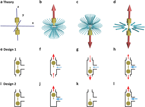
Pumps drive fluid through a localized motion; a 1D oscillator is the most simplified localized motion (Figure 1a). The oscillator pushes fluid in the z-axis direction, attracting fluid to supplement (Figure 1b,c), forming outflux and influx. The flux is proportional to the vibrating frequency. Mathematically, the flow field of the oscillator is consistent with its symmetry and is a mathematically ideal pump or the simplest mathematical pump (SMath pump) (see Movie S1 and Figure S1, Supporting Information). The inlet flux and outlet flux of the SMath pump are introduced into the microchannel through the guide wall (Figure 1e–i), and the SMath pump becomes the microchannel pump. The flow field of the SMath pump is 3D and can be designed in many ways. For example, a pump with one inlet and two outlets (Figure 1e–h) or a pump with one inlet and one outlet (Figure 1i–l). For the oscillator, it is best to use a sphere, which is easy to roll and reduces friction loss and the possibility of blockage.

Figure 1
Open in figure viewerPowerPoint
The oscillator and its long-term effects on the fluid. a–d) The vibrating oscillator in 3D space (a) pushes fluid up (b) and down (c), attracts the fluid from all directions, and forms long-term influxes and outfluxes (d). The flow can be introduced into the channel through the guide wall, and e–h) design 1 (one in and two out) or i–l) design 2 (one in and one out) can be obtained. The olive color represents the oscillator and its movement, the red represents the outlet microflow, and the blue represents the inlet microflow (see Movie S1, Supporting Information).
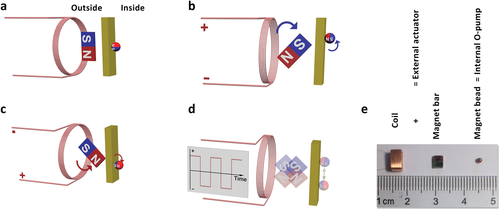
We use scanning magnetic field technology to manipulate a magnet bead as an oscillator pump (O-pump) for real applications. The pumping system consists of two parts: an internal rolling magnet bead as an O-pump, an external actuator that includes a magnetic coil with a rotatable magnet bar (Figure 2a). When the square wave signal arrives, the magnet rotates to generate a scanning magnetic field (Figure 2b,c). The O-pump's roll at the lowest energy point with the swinging magnet bar forms an oscillating movement (Figure 2d). The rolling technique minimizes resistance, minimizes parts wear, and maximizes reliability. We estimate the minimum power consumption by the frequency, the O-pump, and the magnet bar (see Supporting Information). The measured power consumption by an MP3 player is less than 10 mW (see Figure S4, Supporting Information).

Figure 2
Open in figure viewerPowerPoint
The principle of electromagnetic control. a) The outside magnet bar exerts forces on the inside magnetic O-pump, directing it to the lowest energy position and orientation. b,c) When the current arrives, the magnet bar swings to a new angle, and the O-pump rolls to a new position. d) The square wave signal makes the O-pump vibrate. e) We use a 5 mm coil with a 3.5 mm magnet bar as the actuator and a 1.5 mm magnet bead as an O-pump (see Movie S2, Supporting Information).
With a 1.5 mm O-pump in a square container and a 3–5 mm actuator beneath (Figure 2e), we show the flow field (Figure 3a). The O-pump moves north to south at 1 Hz. As the frequency goes up to 16 Hz, the flow speeds up, and the flow field gets more stability because of the fluid inertia (Figure 3b). We move O-pump close to the wall, the corner, or the bottom (Figure 3d–f). The flow field remains its basic shape under different boundary conditions. We can easily design the boundary to guide the flux in and out (see Movie S2, Supporting Information).

Figure 3
Open in figure viewerPowerPoint
The flow fields of a 1.5 mm O-pump. a) By image inverting, the particles in the liquid show the flow field (1 Hz). b) When the O-pump vibrates from 1 to 16 Hz at different places, the flow field keeps unchanged, but the flow becomes strong. The flow field has a similar shape c) near the left border, d) at the corner, and e) on the bottom (see Movie S3, Supporting Information).
It is not easy to measure the freely moving O-pump's liquid pressure difference. Gas pressure transmits to the pressure sensor quickly. Therefore, it is easier to measure the flow field in the air than in the water. We fabricate a polymethyl methacrylate (PMMA) chip with a sealed 2 mm channel (Figure 4a). The pressure difference generated by the O-pump at the T-shaped intersection is transmitted to the pressure transmitter through a 0.5 mm silicone tube. The fluctuation of atmospheric pressure will reach 100 Pa, and the pipeline's deformation causes significant pressure fluctuations. We close the laboratory's doors and windows, write software to automatically control the O-pump, and obtain and calculate the differential pressure data to get an accuracy of 0.1 Pa (Figure 4b and Figure S5 and Movie S4, Supporting Information). The flow field pressure difference of 0–4 Pa is proportional to the vibrating frequency range of 0–16 Hz. We did not see any significant differences among different gases. The pressure difference of 4 Pa at 16 Hz is equivalent to a gas of one atmosphere compressed by 0.004%.

Figure 4
Open in figure viewerPowerPoint
The flow field differential pressure (ΔP) to the frequency. a) We use a PMMA chip with merged output channels. The O-pump vibrates at the three-way intersection. Two 0.5 mm silicone tubes (red and blue) transmit the differential pressure (ΔP) from the input channel (Px) and the merged output channel (Pz) to the sensor. The computer automatically coordinates the square wave commands and the data collections for noise reduction (see Supporting Information). b) The relationship between the gas differential pressure is generated by O-pump and the O-pump vibration frequency (see Movie S4 and Zip S1, Supporting Information).
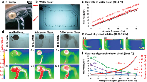
To accurately obtain the pump's performance, we measure the flow velocity in a single circulation channel (Figure 5). Driven by the 0–25 Hz square wave audio, the O-pump drives water with plastic particles to form a flow (Figure 5a,b). By tracing the plastic particles, we calculate the flow rate (see Movie S5, Supporting Information) and react to actuator frequency (Figure 5c). A single channel is only for the measurement of the pump output. This system is easy to expand into a channel network. We prepare a reference book for readers to design chips (see Figures S2 and S3, Supporting Information). O-pump adopts the simplest structure (a sphere) and the simplest movement mode (1D vibrator), which can work directly in the rigid channel without contacting its inner wall (Figure 1e–l). In theory, this design should be able to cope with the harshest fluid environment and have the most extended life. We put debris (Figure 5a,b), bubbles, and paper fibers into the pump's working area (Figure 5d) to test whether the pump can still work as usual. We add glycerol to the water to simulate human blood's working conditions (the dynamic viscosity[40] of human blood is 3–5 times the water; see Figure 5e,f). The results show that the pump can work in harsh conditions, and the slowing of the flow rate is caused by the increase in viscosity or fiber resistance. We have repeatedly monitored the pump's continuous 10-h driving on fluids containing plastic debris and salt and have not found noticeable wear or loss of control of the pump (see the 7-s Movie S6 for the 4-h experiment record, Supporting Information). In actual cell culture experiments, this kind of pump typically works for more than 7–45 consecutive days (programmed, not continuous vibrating) many times in 2020–2021 (the cell culture medium contains various debris and complex ingredients).

Figure 5
Open in figure viewerPowerPoint
The O-pump system and its flow rate measurements. a,b) The O-pump vibrates and pumps the liquid in the T-shape channel of a channel loop. c) By tracking the plastic particles’ movement, we obtain flow rate by the average flow velocity and the channel cross-sectional area for the relationship to the pumping frequency (N = 75, k = 1.125 ± 0.011 µL s−¹ Hz−¹). The pump's durability is tested by putting a) debris, d) air bubbles, and paper fibers in the channel. d–f) The simulated blood's viscosity is achieved by adding<60% glycerol to the water. The width of the channel is 1 mm, and the depth is 2.5 mm. The average velocity of the laminar flow in the channel is calculated as half of the maximum velocity. 100-nm nanoparticles are used to indicate manifold and maximum flow rate. d,e) The false-color image is obtained by calculating each pixel's absorbance (see the color scale). f) Error bars indicate the standard deviation of three replicates. Tests are at room temperature (20 ± 1 °C) using a 1.88 ± 0.07 mm O-pump (sphericity < 1.003, see Movie S5, Supporting Information).
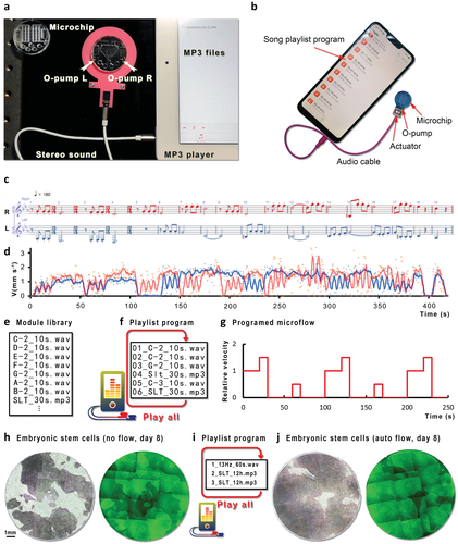
O-pump is very power-saving (<10 mW) and can be directly driven by a mobile phone or MP3 player's audio. We have designed a music operating system for this purpose, convenient for a microchip with two O-pumps to use through audio interface programming. Like an IC-OS-APP (integrated circuit-operating system-application software), a MOC-MOS-MAP (the microfluidic chip-music operating system-music application software) system is appropriate for an O-pump microchip. We rearrange the first movement of Beethoven's “fate” into a two-part work and transform it to a 4 h 2 m 14 s *.wav file so that an MP3 player or mobile phone (Figure 6a,b and see Movie S7, Supporting Information) can control two O-pumps by stereo audio. Beethoven's four-note motive slightly tilts upward because of the fluid's inertia (Figure 6c,d). We build a library by speed and time (Figure 6e). When programming, we copy and sort these units as a playlist to form a completed program (Figure 6f,g). For example, C-2_10s.wav is a module that produces a rate of 1 for 10 s (v = 1, 10 s). Combining other modules in the module library, such as G-2_10s.wav (v = 1.5, 10 s), C-3_10s.wav (v = 0.5, 10 s), and SLT_30s.mp3 (v = 0, the 30 s), results in a playlist at loop mode. When the MP3 player plays this playlist, the microfluidic chip programs its flow (Figure 6g). The playlist is a standard function of mobile phones, iPads or iPods, MP3 players, and computers. Anyone can use it and program the microflow without learning and obtaining any special equipment. The O-pump system is very stable and energy-saving, and the MP3 control has not found any problems after continuous testing for several months. We used Beethoven's music to monitor the constant working status for more than 4 h (durability test, see Movie S6, Supporting Information). O-pump can keep working even when the channel is crystallizing and becoming dirty. We apply this music operating system to the culture of embryonic stem cells and compare the results of 8 days of culture under the music operating system's control. We confirm that this kind of sophisticated programmed automatic culture has a significant advantage over no-flow culture because stem cells’ growth rate increased by about twice (Figure 6h–j).

Figure 6
Open in figure viewerPowerPoint
Music programming operating system. a) The microchip is on a shelf with two built-in actuators (L: Left sound channel; R: right sound channel) (hand mirror shape). We then put the O-pump into the chip and use the audio cable to connect to the a) iPad or b) a mobile phone. c,d) Music notes (c) converted into square wave files (<30 Hz in this case) can drive the fluid in the chip (d). e–g) A convenient way is to build a music library (e) with various lengths and frequencies and use the loop function (f) of the playlist to drive the microflow (g) in the chip programmatically (see Movie S7 and Zip S2, Supporting Information). h–j) Among embryonic stem cells cultured without flow (h, the green fluorescence, and bright-field), under the precise control of programmed microflow (i), the growth rate is doubled (j).
The SMath pump has a precise mathematical concept. It helps us to clarify the evolution route and research and development direction of the micropump. We obtain an ideal micropump based on the SMath pump theory, reducing the micropump to 1 mm (oscillator pump, O-pump), the external device (actuator) to 5 mm, 10 mW. This system costs ≈$10 and can work in harsh fluid environments (such as animal cell culture) for an extended period (a few months of testing). An MP3 player drives two O-pumps by a programmable playlist. O-pump is a permanent magnet positive sphere in an open fluid space, which is not easy to block. It rolls freely without wear. Only controlled by the magnetic field, it avoids interference from the current, electric field, and chemical activity. The fluid is driven by vibrating motion, in open or sealed channels, with no unique materials. The O-pump output is proportional to the audio driving actuator's driving frequency, and no other equipment is needed. For MP3 playlist programming, no professional training is required. The system requires only a magnet sphere and a matching scanning magnetic field, which can be applied in different scenarios as needed, such as the long-term automatic cultivation of stem cells or point-of-care devices.
Barium ferrite<2 mm particles were taken and grinded in an automatic grinder to obtain a perfect sphere. When the particles rolled freely on the glass plane, they met O-pump requirements.
Like O-pump, there was no material restriction for magnets. Neodymium magnets were used. The 3–5 mm magnet was fixed inside the coil with a swingable plastic bracket. When the current in the coil changed, the magnetic field of the coil guided the magnet to swing, generating magnetic field scanning.
White plastic particles were made by cutting plastic to debris of ≈0.1 mm, indicating the fluid's movement. The movement of particles was recorded and the distance was manually measured and the speed of particle movement was calculated. Since the microchannel's laminar flow had different velocities, the ten fastest particles were taken for measurement and the average value was found.
The cell line used for cell culture in microfluidics was hESC-H9-eGFP-AAVS1 (CA4026106, Beijing Cellaby Biotechnology Co., LTD). Stem cells in microfluidics used both the artificial cell nest technology from the authors’ other article, “Design artificial stem cell nests for stem cell niche in a microfluidic petri dish programmed by a cell phone,” and the pump technology described in this article. The O-pump described in this article was put into a petri dish and an MP3 player was used to program and control the petri dish's circulation, turning the petri dish into a microfluidic petri dish. A semi-enclosed 10-mm diameter cell nest was designed in the microfluidic culture dish. The microcirculation in this cell nest could bring nutrients to the deep cell nest. The fastest speed of microcirculation was less than 40 microns per second. The half-life of the cell nest to retain the internal material was 23 min. The MP3 playlist was used to program (1 min day−¹) to ensure fresh medium outside the cell nest went into the cell nest. The consumption of medium was about five drops every 2 days. The culturing of embryonic stem cells in cell nests was similar to the traditional method, but the amount of culture medium and cells was minimal. Matrigel (4 °C, Matrigel Matrix hESC-qualified, REF 354277, LOT 8281007, CORNING) and DME/F-12 1:1 (1X) medium (4 °C, containing L-glutamine and HEPES Buffer, HyClone, LOT AD11223266) were prepared. 100 µL of Matrigel was added to 6.9 mL of DME/F-12 1:1 (1X) medium on a 0 °C platform or on ice to obtain a 1/70 Matrigel dilution. After the sterilized microfluidic petri dish was precooled (on a 0 °C platform or on ice), ≈150 µL of the Matrigel dilution was dropped into the cell nest to cover the bottom of the cell nest and place the microfluidic culture dish in an incubator (5% CO2, 37 °C). After 1 h, the cell nest supernatant was removed and 2 mL of PGM1 stem cell culture medium (CA1007500, Beijing Cellaby Biotechnology Co., LTD) was added to cover all channels. The stem cells cultured in the T12.5 cell culture flask were digested and resuspended by 3 mL PGM1 stem cell culture medium, and only one drop of the cell suspension (containing ≈1% of the total cell flask cells) was added into the cell nest. The microfluidic culture dish containing cells and culture medium was then placed at room temperature without disturbance for 15 min (20 °C) and placed in an incubator (5% CO2, 37 °C). After 24 h, the MP3 audio program was started by playing the playlist in an MP3 player (1 min day−¹, 13 Hz) for automatic microfluidic culture, and 100 µL or three to five drops of PGM1 stem cell culture medium was supplemented in the channel outside the cell nest every 2 days without disturbing the cell nest. Microscopic pictures of the cell nests were obtained every 2 days, and the operation time outside the incubator was ≈15 min.
A self-editing software was used to obtain each pixel's red-green-blue value and calculate the absorbance value. According to the color scale, the absorbance value was converted into a false-color value to form a false-color image.
Readers could send requests via email (contact@qiyuexm.com) for microfluidic petri dishes, O-pumps, actuators, plastic particles, and MP3 audio files.
For more detailed methods (such as gas differential pressure measurement) and data, please refer to Supporting Information.
The authors thank the National Natural Science Foundation of China (40776082 and 31371444) and Xinchuang Biotechnology (Xiamen) Co., Ltd. The authors thank Prof. Donghui Li and Prof. Ping Huang, Xiang You, School of Medicine of Xiamen University for microscopy. Xiamen Qiyue Electronic Technology Co., Ltd. supported this work. Figure 6 was replaced on June 4, 2021 with a higher resolution version of the same image. The scientific meaning of the figure is not changed.
The authors declare no conflict of interest.
X.Y.(L.)P. (experiments and manuscript); L.P. (music technology); Y.G. (measurements).
SOURCE:https://onlinelibrary.wiley.com/doi/10.1002/admt.202100150
没有上一条信息
